 |
| May 22, 2018 | Volume 14 Issue 19 |
Designfax weekly eMagazine

Archives
Partners
Manufacturing Center
Product Spotlight
Modern Applications News
Metalworking Ideas For
Today's Job Shops
Tooling and Production
Strategies for large
metalworking plants
Engineer's Toolbox:
3 control schemes for step and servo motors that optimize the operation of positioning conveyor systems
Most belt conveyor applications operate at either a fixed or variable speed with velocity controlled from the main drive motor. Positioning systems such as edge-belt conveyors (used for PC board assembly and automated check weighing) require more than velocity control. The main drive motor must start/stop the conveyor with a moderate to high level of precision to address the positioning requirements of the application.
Attaining this level of positioning control requires more than a standard DC or AC motor. Step motors and servo motors are the best solutions because of their precise positioning capabilities. The multiple I/O points and numerous network connections offered by modern step and servo motor drives also make them well-suited for positioning conveyors.
Different control schemes exist to ensure precise motor positioning and speed. Here are three control systems to consider when implementing a step or servo motor for optimum use in positioning conveyors.
1. Pulse control: Most common method
The most common method for controlling any step or servo motor, including those used in positioning conveyors, is using a simple digital pulse control, also known as step and direction control. If the primary PLC (programmable logic controller) or controller in the system has one or more high-frequency outputs (20 kHz or higher), pulse control is a good option.
The pulse output* from the PLC connects to the Step input of the motor drive or integrated motor while a second, non-pulse output ties into the Direction input. The pulse number and frequency transmitted to the Step input determine the conveyor travel length and speed, respectively. The signal (high or low) at the Direction input determines the travel direction (forward or reverse). For smooth conveyor starting and stopping, the PLC/controller must ramp the frequency of pulses up and down to create smooth acceleration and deceleration ramps. Without this modulated pulsing, the conveyor will jerk when starting and stopping.
*A 20-kHz pulse output frequency is minimally required for Step and Direction control. Typically, 100 kHz or more is ideal. Many controllers offer frequencies as high as 2 or 3 MHz. While high-frequency outputs are desirable, they usually cost more. When using lower frequency outputs, choose a stepper drive or integrated stepper motor with Microstep Emulation that enables a smooth, microstep operation.
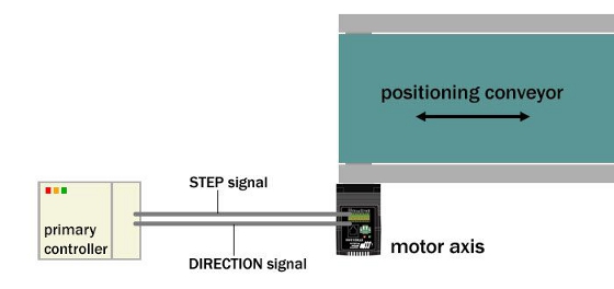
Graphic 1: Shown is a configuration of using pulse control when implementing a step or servo motor in a positioning conveyor. The primary controller creates both Step and Direction pulse signals that determine the conveyor travel length and speed. For smooth positioning conveyance, the PLC/controller must ramp the frequency of pulses up and down to create smooth acceleration and deceleration ramps.
2. Velocity control with analog input offers more flexibility
A variation of discrete I/O signals is another popular method for controlling step and servo motors used in positioning conveyors. This approach uses one or two digital inputs plus an analog input. The first digital input is a Run/Stop signal that prompts the motor to ramp up and operate at a targeted velocity until the input is reset -- at which point the motor decelerates to a stop. Motor ramp acceleration and deceleration rates are configured in the software during axis commissioning and, therefore, controlled by the axis. A second digital input can control direction (forward/reverse).
While motor target velocity can be software configurable to a fixed value, many users prefer to control conveyor speed with an analog signal because of its flexibility. Using a trimpot wired to the drive's analog input, the machine operator can accurately control the conveyor's target velocity for different process conditions. The configuration includes scaling the motor's speed range to the voltage level at the analog input. The analog velocity control scheme offers a very effective method for controlling both position and speed of the conveyor using a minimal number of I/O points. It is also very simple to program at the PLC or primary controller.
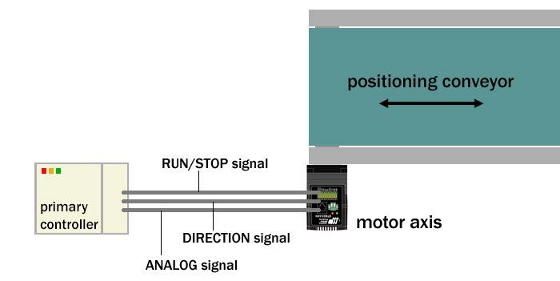
Graphic 2: This configuration outlines how a primary controller provides RUN/STOP and DIRECTION digital signals, as well as an ANALOG signal for velocity reference to the motor axis to control the run/stop operation of the positioning conveyor.
3. Network control (distributed control) commands the process
Network control provides considerable flexibility for controlling the step motor or servo motor in positioning conveyors. This control scheme makes a permanent serial or Fieldbus connection between the primary controller and the motor drive or integrated motor. It replaces all or most of the discrete I/O signals used in the previous two control schemes.
In many drives and integrated motors, network interfaces include RS-232, RS-485, Ethernet TCP and Ethernet UDP, EtherNet/IP, Modbus, and CANopen. For single-axis applications where the primary controller controls only one axis, any of these serial interfaces work. For multi-axis applications where control must be of more than one axis, all but RS-232 are usable.
Once establishing the network connection, the primary controller sends commands to the motor axis. The exact details of the commands vary by the connection method. For this discussion, we'll say that an RS-232 or RS-485 connection is used to send SCL commands from the primary controller to the axis.
SCL is a simple proprietary command set defined with two letters and following a simple syntax easily adopted by programmers. The syntax for streaming an SCL command over an RS-232 or RS-485 connection looks like:

In this example, the command FL represents Feed-to-Length and represents an incremental or relative move command. The number 20000 is the distance parameter for this command and indicates 20,000 increments of motion. For a step motor, each increment represents one step, while for a servo motor, each increment represents one encoder count. (You'll need to convert steps or encoder counts in the motor to a linear distance of the conveyor.)
 at the end of the string symbolizes a carriage return (ASCII 13), which designates the end of the command string. Upon receipt of this command string, the motor axis indexes the conveyor forward a distance of 20,000 increments.
The SCL command set contains additional commands for velocity, acceleration, and deceleration, as well as movement in both forward (positive) and reverse (negative) directions. More than 100 commands are available in SCL, including those for absolute moves, registration moves, and much more. (This Host Command Reference serves as a dictionary for SCL commands.)
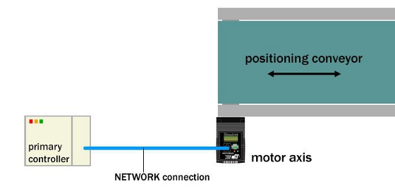
Graphic 3: Network control offloads control functions to the motor axis. This diagram shows the network connection between the primary controller and the motor axis.
Choosing among these three schemes to control position conveyors with step motors and servo motors is a personal choice and often guided by the designer's unique requirements. While choosing a step motor or servo motor to drive the conveyor is determined by the application, step motors are considered for smaller conveyors, while larger conveyors often require servo motors. Discussing specific application requirements with an expert in motion control is always a good place to start.
Published May 2018
Rate this article
View our terms of use and privacy policy